
On-bottom roughness analysis
Need for this analysis
Subsea pipeline free spans can become a challenge in pipeline design and operation due to uneven seabed or seabed scouring effects. Determination of allowable free span length plays a crucial role in design of offshore pipelines. The spanning-led oscillation can fatigue the pipeline and eventually result in catastrophic failure like a hydrocarbon leak at the weak spot, which is generally the pipe joining girth weld.
The strength failures of the spans are generally caused by the following:
self-weight
hydrodynamic loads
the anchor dragging or fishing gear lateral imposed load
The pipeline on-bottom roughness analysis is conducted to determine the pipe stress and the associated fatigue damage due to internal pressure and temperature fluctuation and vortex-induced vibration (VIV) of free span sections due to seabed unevenness.
Our analysis method
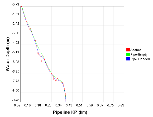
We analysed the on-bottom roughness analysis of the 24” subsea pipeline (WT = 20.6mm) installed on a highly uneven sea bed terrain. Allowable free spans for the empty and flooded conditions were determined as per requirements of the recommended practice DNV-RP-F105 (Free Spanning Pipelines). To assure that the installed pipeline spans are lower than acceptable spans length, on-bottom roughness analysis was carried out using iDG10 developed state-of-art platform called Subsea Pipeline Design Tool (SPDT). All required input data for the analysis were saved in the SPDT centralised database. The pre-processing and post processing steps were carried out in the SPDT.

Result
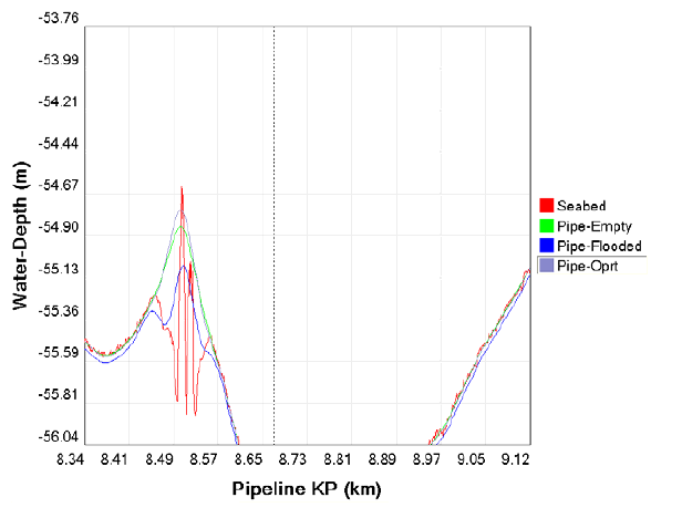
The integrated on-bottom roughness analysis module of SPDT allows engineers to easily configure the pipeline-seabed model by extracting relevant data viz dimensions, geo-technical, bathymetry, hydrodynamic loads etc. from the project centralised database. Once the model is set up, using ANSYS solver the simulation is completed and results are processed using SPDT post-processing module.
The process sample results for the presented case study are shown in figures below.


Lateral bucking analysis
Need for this analysis
The accurate prediction of lateral buckling is crucial for offshore pipelines that are subjected to high temperature, internal pressure and complex pipe-soil interaction. The Hobbs analytical method for lateral buckling of ideal submarine pipelines is widely used in industry to predict the behaviour in early design stages. This analytical solution considers perfect straight pipelines, ignoring the seabed natural unevenness. The objective of this case study is to evaluate effect of the seabed natural unevenness on the pipeline lateral buckling behaviour.
Our analysis method
We analysed the effect of the uneven seabed on the 24” (20.6mm WT) pipeline’s lateral buckling behaviour. After review of the subsea pipeline using the Hobbs’ analytical method, FEA simulation was carried out to investigate the effect of the actual seabed terrain on the pipeline lateral buckling behaviour. The lateral buckling analysis FEA using the pre and post processing features of the SPDT was carried out in ANSYS.
Results
On completion of preliminary lateral buckling screening assessment using SPDT Hobbs model, further detail analysis was carried out in SPDT integrated FEA global buckling module. The pipe-seabed configuration was modelled automatically by extracting relevant inputs viz pipe dimensions, soil properties, bathymetry, operating conditions, metocean etc. from SPDT centralised database.
The configured model was simulated in ANSYS solver and the results shown in figures below are processed using SPDT post-processing module in an efficient manner.


Seismic assessment
Need for this analysis
The design of subsea pipeline becomes more complicated in areas of moderate or high seismicity, due to the various types of seismic loading. Seismic waves can cause damage to unburied pipeline systems, especially in the interfacing area, such as in the pipeline transition section from buried-to-unburied and the pipeline tie-in spool to the subsequent structure. Therefore, to ensure the pipeline integrity over its design life, it is important to design the pipeline considering relevant geographical seismic loads in combination with the other operating conditions. This case study presents the results of the 24" pipeline having transition in the seismic zone.
Our analysis method
To assess the seismic responses of a 24” hydrocarbon export pipeline, full transient dynamic analysis (i.e. time-history loading) over the entire pipeline length is performed using finite element programme ANSYS.
In the FEM model, both covered (trenched) and uncovered sections of the pipeline with varying concrete thicknesses are taken into consideration. The seabed bathymetry along the pipeline route is modelled using non-linear springs to restrain pipeline movements along axial, lateral and vertical directions. The pipeline elements are initially aligned straight by the spring’s elements, nodes of which are then displaced vertically to define the seabed roughness.
For trenched pipeline and exposed sections, the pipe to soil axial, lateral and vertical interactions are modelled using non-linear uniaxial springs. Whereas, to model free span sections the soil spring elements were deactivated in the identified spans KP locations.
The vertical springs stiffness used for modelling the soil’s behaviour are determined based upon DNV-RP-F110 (Global buckling of submarine pipelines) recommendations and under the assumption that the upper layer soil along the pipeline route mainly comprised of sand and clay mixture.
The axial and lateral spring stiffness (to restrain pipe movements) is defined as the product of pipe submerged weight and coefficient of friction for the uncovered pipeline sections. Whereas for the trenched sections, the axial, lateral and vertical spring (uplift) resistance are determined considering the backfill sand height.
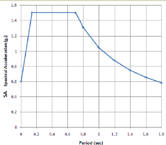
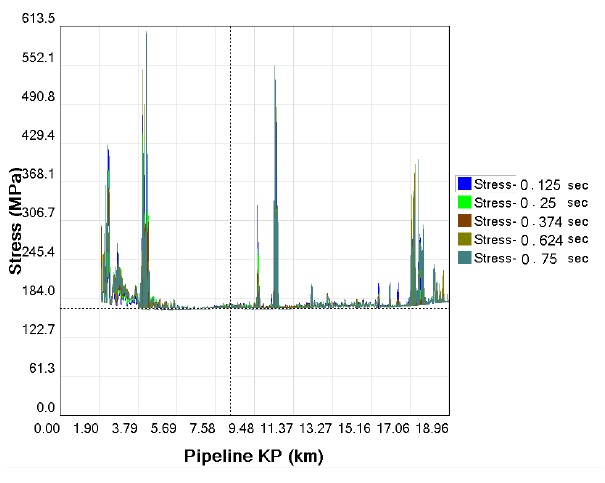
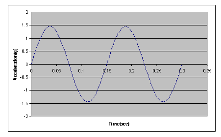
The full transient dynamic simulation method adopted for seismic analysis of the presented pipeline case study involves the actual solution of the dynamic equation of motion throughout the duration of the applied load and subsequent system vibration, providing a true simulation of the system response at all times. To obtain time history excitation of the pipeline, time history ground acceleration are obtained from acceleration spectrum graph for Functional Evaluation Earthquake Ground Motion (FEE)) of project pipeline offshore route and are applied uniformly all along the pipeline route. Considering the complex non-linear nature of the transient dynamic simulation method (which is always computationally intensive), four acceleration spectra are used to represent simplified sinusoidal time history ground accelerations for a duration of two wave periods as shown below.
Results
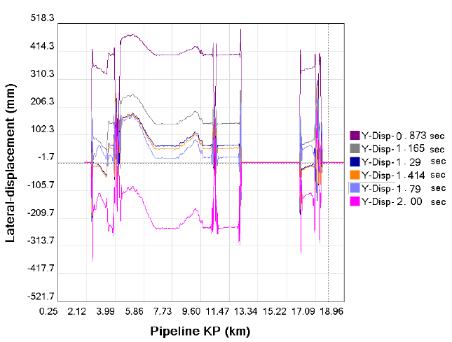
To design pipeline against seismic loading conditions, SPDT provides user friendly interface to configure pipe-soil FEA model and seamless interface with ANSYS solver to simulate transient problem in hand. The results, viz transient lateral displacement, and stresses of the pipe section within the transition (buried to exposed) processed by SPDT are presented in figures below.


Comments